
I also want to use the same design rules I generally try to, i.e. as much printed as possible. For this though there will have to be some compromise because you can't print a servo. I also wanted to make it in as short a time as possible and I gave myself 48 hours. Time to rummage around for parts. In it's simplest form I need the following parts
- Arduino microcontroller to control things (this one)
- Battery clip and battery for power (this one)
- Small servo to move the finger (this one)
- Chunky switch to trigger the finger (this one)
I would have liked a smaller switch as this would have given me more movement opportunities, but this is what I had to hand. Also, I would have liked an external switch so as not to need to disconnect the battery, but the only one I had was huge so I left this out and will address in version 2. I also fancied an LED or two. Either one inside to light up all the gubbins when switched "on" or one on the case to denote an "on" state. Again I left these out for version 2. Adding holes in the walls is really quite a simple task but the added complexity of the wiring and trying to work out space issues was something I could add later. Prototype first.
The basic idea is simple, it's a box that opens in the middle. The first design challenge then is how big does this all have to be. I measured the micro controller and tried to work out on a bit of paper the clearances for the servo and switch, then pretty much guestimated to the next centimeter. Then added a 5mm wall all round. Yep it'd be chunky, but I do like to over-engineer strengthy stuff.
The next design challenge then, is the hinges. Most of the boxes you see on the net use jewellery box style hinges. I want to print as much as possible so the first option was a dimple hinge. There was a real fine line between sticking out enough to grip but not far enough that you force the edges of the lid and break them. A bit like this in actual fact.

Poop. Ok, plan B - proper hinges. I was hoping to avoid the complexity but I didn't want to try and debug the dimple hinges. Besides there is a fair bit of risk that they may not work when you put it all together. I'm 5 hours in at this point so proper hinges, and don't forget to over engineer the strengthy bits. 10 hours in and I have my proof of concept.


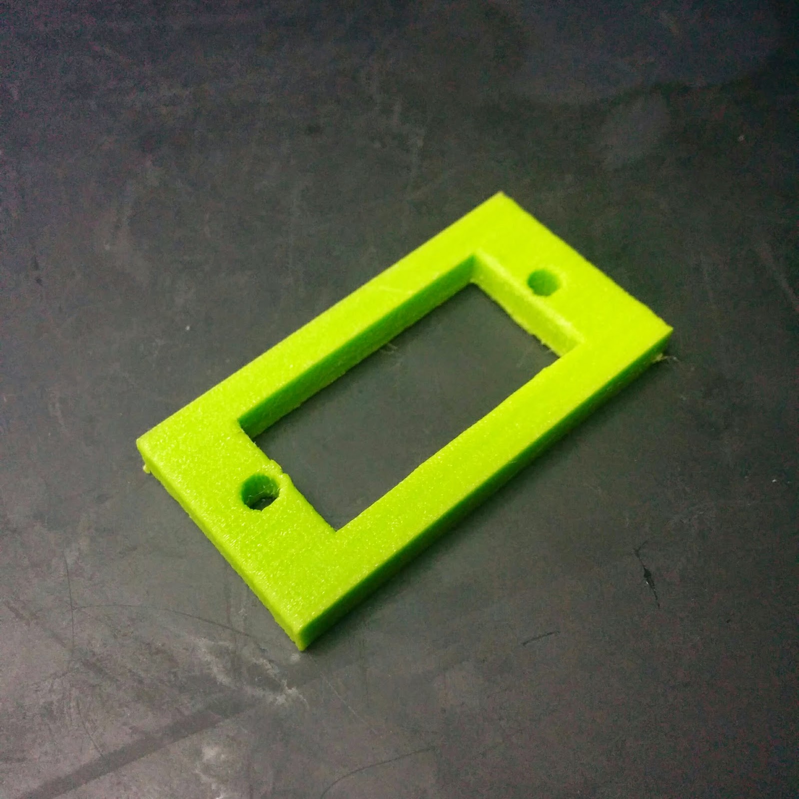
14 hours in and they are attached to the model in Blender with a split lid. Time to focus inside the box. The microcontroller needs a good measuring and a few pins to locate the board in the bottom of the box. I was thinking of a way to lock the board in place, but I'll focus more on that in version 2. I think a simple plug over the pin will do, but back to version 1. Sixteen hours in and we have a test plate.


Nineteen hours in and I have printed a cross section of the base with the lugs for the microcontroller and battery ready for a fitting test.


The next item to design a holder for is the servo. I've often wondered why servos have the wire coming out where they do and I always remember the trouble you have fitting some of the smaller ones. For example, when you put the end with the wire in, you need to rotate the body to get the other side in... but the attaching lugs are to close to make that easy:

So the only thing for it is to take off the bottom and slide the servo in. I'm worried that with all the torque the arms will snap, but it eventually fits, so I can move on.

So at 23 hours I'm thinking things are going quite well and judging by the estimates for printing the box I have about 8-9 hours of fiddle time left. So the finger will get the majority of this. The challenges here are really the fitting of the item in the box with enough move to rotate while being strong enough to handle the torque. I wanted the smallest possible box I could get so I decided to mount the servo to the underside of the other lid part. This also provides some safety so that the servo won't crush the microcontroller. Because of the space, the switch and servo need to sit next to each other. This means the part of the finger that attaches to the servo horn needs to be pretty thin, but the finger part needs to extend out round the switch. not only torque now, but more annoying physics called moments. Anyhow, best I could do by hour 27 was this.


This did give me a couple of real good indicators of corners I could shave to make tolerances a lot better in the final product.
Adding everything I have so far we're going into the final stretch, an integration test of the complicated lid is now on the cards. By hour 32, I had the lid printed and the bits attached and was able to do an integration test to test the angles I had designed. It was at this point that I could finally see how the servo would cope with the force required to move the chunky switch.


At this point all I'd had sleep-wise was a few hours in between printing. Now I had a big 9 hour print to go for the main box and hinge pins, I could finally get some shut-eye. The only things left to do were solder the electronics and assemble the whole thing. And I'm going to have a few hours spare for some more sleep, or, more likely fix any issues like warped hinges.

43 hours from concept to item.
[video coming soon]
No comments:
Post a Comment